
This section defines the baseline rescue system used by EPCSAR. This does not set an exclusive standard, and variations will be made depending upon the situation and specific equipment available at the time. The purpose of this section is to establish a baseline system that will work in the vast majority of rescue situations and is known and understood by all fielding members. This section specifically discusses the systems themselves. Attachment of the litter is covered in a subsequent section.
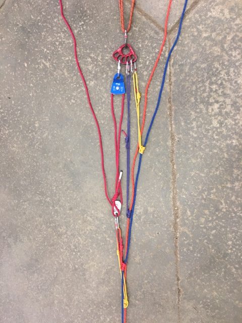
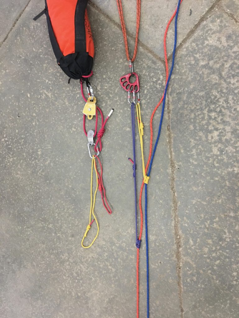
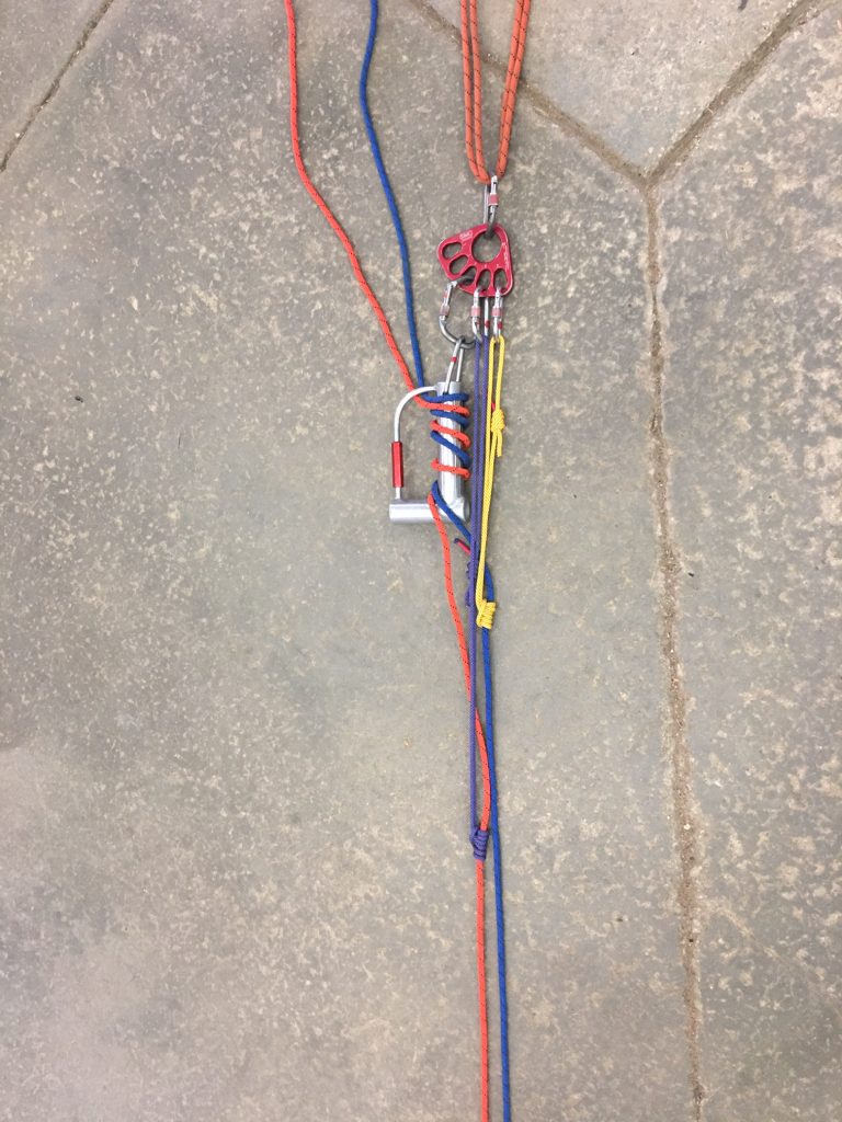
A good summary of our systems can be seen here:
One extremely important aspect of safe, efficient, coordinated technical rescue is a consistent set of commands. Commands used during the operation of rescue systems are covered in “Rescue Commands”.
Each team vehicle contains one or more rescue packs which contain the equipment shown in the image below. All of the systems discussed in this section can be built using the equipment in the rescue pack.
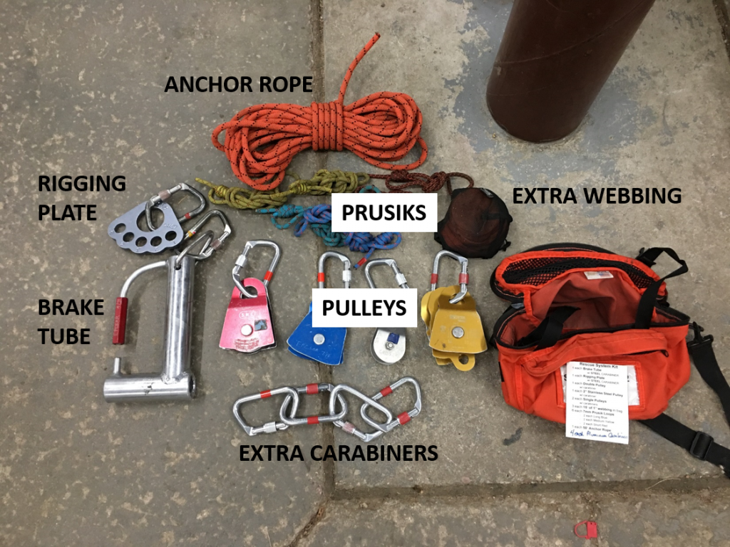
Rigging Plate

Rigging plate with brake for lowering system 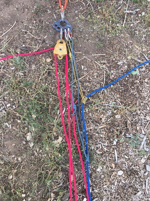
Rigging plate with uphaul system
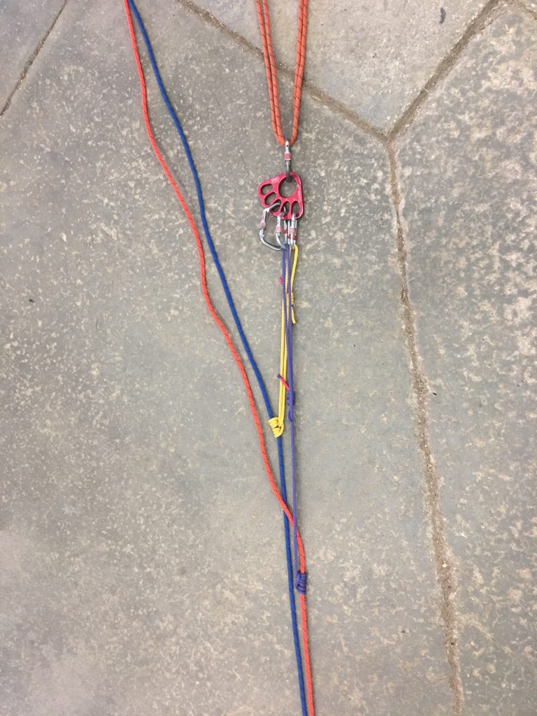
While not strictly necessary for any of the baseline rescue systems, the rigging plate (AKA Bear Claw) makes building an uphaul system more convenient. In a simple lowering system, the rigging plate doesn’t serve much purpose as the brake is the only device connected to the anchor. In an uphaul system, there will likely be at least a pulley and two carabiners for ratchet prusiks (explained shortly). The rigging plate keeps this more organized than just connecting everything directly into the anchor. A lowering operation may require an uphaul at some point, and if the rigging plate is in the system, the addition of the uphaul system is much easier and keeps the system more organized. The rigging plate should have a steel carabiner attached to it in the rescue pack. If a full rescue load is anticipated and a steel carabiner is not available, two aluminum carabiners of the same size should be used.
Low angle lowering system (AKA Scree Evacuation)
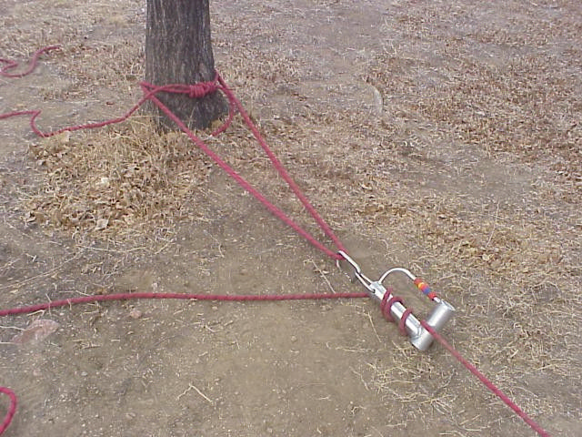
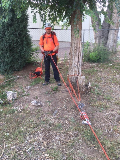
A lowering system consists of an anchor, a brake, a load line and a load (usually a litter, patient and litter bearers). Typically, the anchor will be a Wrap 3/Pull 2 anchor or basket anchor around a tree. If a boulder is used, usually a 200 foot rope will be used and wrapped around the boulder twice or used to construct a basket anchor. The location of the anchor should be selected so it is suitable for lowering or uphaul.
The brake tube is attached to the anchor with a locking steel carabiner or two locking aluminum carabiners. If two carabiners are used, they must be the same size.
Load Line (rope)
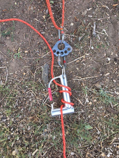
Single rope wrapped on Brake Tube. Red sleeve open while wrapping 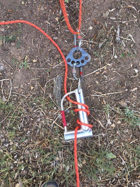
Single rope wrapped on Brake Tube. Red sleeve closed during operation 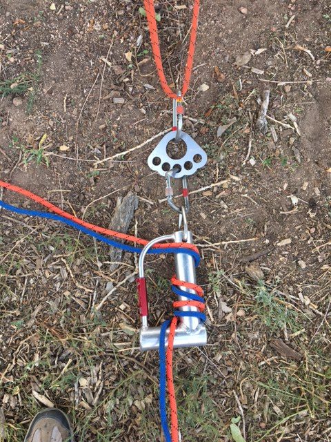
Two ropes wrapped on Brake Tube.
The load line is wrapped around the brake tube as shown. There is a red sleeve on the brake tube that can be opened to allow the rope to be wrapped around the “spine” of the tube. Friction increases with more wraps. Three wraps usually provide the right amount of friction for most rescue situations.
The brake tube easily accommodates a second rope. Two ropes are always used in a high-angle lowering but may be used in a low-angle lowering as well. Consider using two ropes if the lowering will be steep enough that a rope failure would cause injury to the litter bearers or patient. While two ropes will generally be stronger than a single rope, it cannot be guaranteed that one rope will not become slack at some time, requiring that only one rope carry the entire load. A second rope should be considered as a backup rather than reliably increasing the capacity of the system. If two ropes are used, they are wrapped parallel to each other so they feed through the brake alongside each other. It is generally easiest to simply hold the ropes together and wrap both around the tube at the same time. If two ropes are used, it adds clarity of the ropes are of different colors.
Brakeman and Backup Brakeman
The brakeman wears gloves, helmet and eye protection. Brakeman should be some distance from the tube to prevent gloves/fingers from becoming caught in the brake tube. 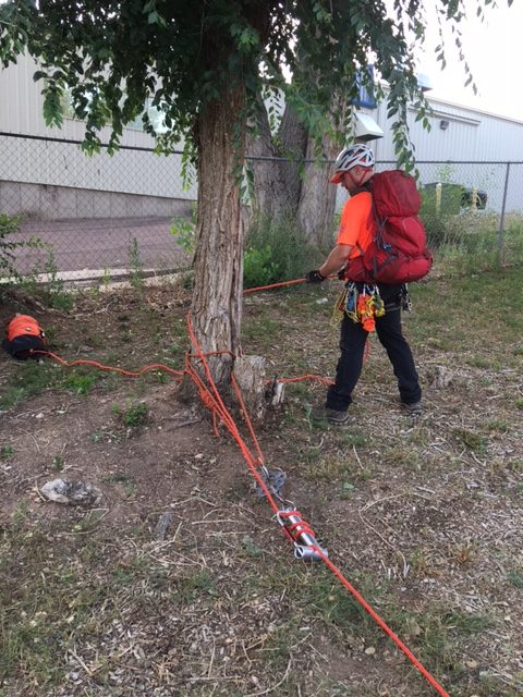
The brakeman can gain additional friction if needed by partially wrapping the rope around a tree.
The brakeman holds onto the rope uphill of the brake and feeds the rope through the brake according to the instructions from the litter (see Rescue Commands). The brakeman wears gloves and never releases the rope(s). The safety and lives of the patient and litter bearers are literally in the hands of the brakeman. A second person takes a position behind the brakeman and serves as a backup brakeman should the brakeman become unable to control the load. The backup brakeman is sometimes called the rope handler because they also make sure there are no knots or tangles in the rope before it gets to the brakeman, but this term minimizes the importance of acting as a backup should something happen to the brakeman.
As long as the brakeman is secure (often seated), there is no need for the brakeman to be tied into an anchor. If the terrain is unstable or there is a significant chance that he/she might fall or otherwise be taken away from the brake, the brakeman should be tied into an anchor. If the brakeman does tie in, he/she should be able to stay with the brake if it shifts position.
The brakeman need not be very close to the brake, and should maintain sufficient distance so there is no risk of his/her fingers or gloves getting caught in the device.
Uphaul System
Uphaul systems are introduced in “Uphaul Systems and Mechanical Advantage”. Uphaul systems can be “inline” or “piggyback”. Inline uphaul systems will be discussed first to illustrate the concept, but the baseline system uses a piggyback uphaul system. Either system is effective but the piggyback uphaul system overcomes some shortcomings of the inline uphaul system.
When a haul team pulls on one end of the uphaul, a “multiplied” force is applied to the load due to the mechanical advantage of the uphaul system. Prusiks are necessary as part of the uphaul system for two specific purposes:
- Ratchet prusiks provide “progress capture”.
- Haul prusiks attach a pulley to the load line to apply raising force to the load line.
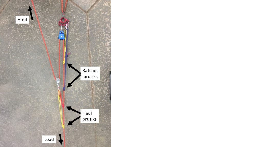
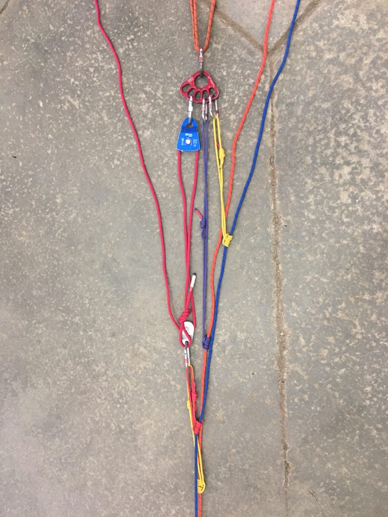
- The load line runs from the litter (load), up through a pulley attached to an anchor
- Tandem ratchet prusiks attached between the load line and the anchor keep the load line (and the load) from moving downhill
- The load line runs back downhill and through a second pulley (the traveling pulley) attached to the downhill load line with tandem haul prusiks
- The load line runs uphill from the second pulley to the haul team or to another pulley and then to the haul team if a change of direction is included.
In the picture, the haul prusiks are very close to the ratchet prusiks. This is only to allow a picture of reasonable size. The load could not be moved much before the haul and ratchet prusiks would interfere with each other. At the beginning of an uphaul, the haul prusiks are moved as far as practical down the load line toward the load. In some cases, the haul prusiks can be moved all the way to the load, but in practice, there is usually some distance between the haul prusiks and the load at least at the start.
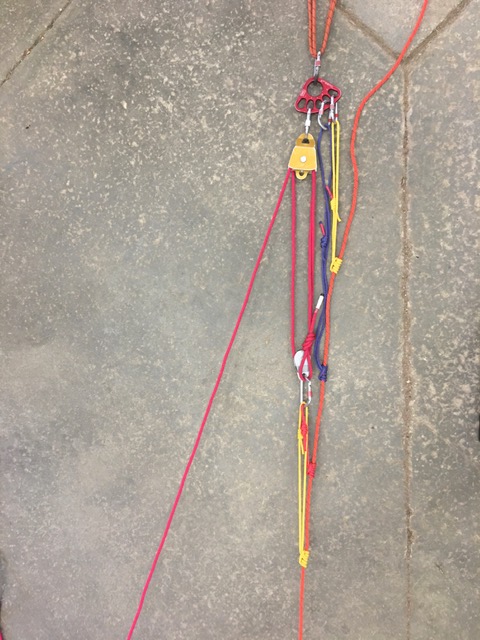
EPCSAR has generally adopted the following convention: Red prusiks are short, Yellow prusiks are medium, and Blue prusiks are long. Each pair of prusiks should consist of prusiks of different lengths. Blue (long) and yellow (medium) prusiks should be used for ratchet prusiks. This combination of prusiks is long enough that they can attach to the load line below a brake tube and attach to the rigging plate. This facilitates easy transitions between uphaul and lowering operations. It also makes it easier to keep the ratchet prusiks away from the pulley. The haul prusiks should generally be yellow (medium) and red (short) as longer prusiks just invite more opportunity for the prusiks to catch on things while traveling with the pulley. This convention is less important than using long prusiks for the ratchet prusiks.
It is necessary to have a prusik minder to tend the ratchet prusiks so they do not get pulled into the pulley connected to the anchor. As the haul team pulls the load uphill, the prusik minder keeps the ratchet prusiks pulled as far down the load line as possible. If the haul team were to release the rope, the ratchet prusiks prevent the load from moving down the hill – hence “progress capture”. Any time the command “STOP” is given by anyone, the prusik minder responds with “SET” to indicate the ratchet prusiks are ready to hold the load.
When the haul prusiks approach the ratchet prusiks, the prusik minder calls “STOP”, and sets the prusiks. The command “RESET” is then issued, which means the haul prusiks are to be moved down the load line an appropriate distance (perhaps to the load itself). Once the reset is complete, the command “RESET READY” means that the system is ready for another “bite” or “fetch”.
The inline uphaul system has some shortcomings:
- If more than one rope length is required, passing knots through the system is awkward and time consuming, especially if the litter must remain on belay
- It is difficult to transition between a lowering system and an uphaul system
Piggyback uphaul system:
The baseline rescue system uses a piggyback uphaul system attached to the load line(s) with prusiks. The load line is attached to the load and secured to the anchor with ratchet prusiks. The uphaul system is constructed using a separate rope. As shown in the pictures, the end of the uphaul rope is connected to the traveling pulley. Tandem haul prusiks attach the traveling pulley to the load line. As discussed regarding inline uphaul systems, the ratchet prusiks should be blue (long) and yellow (medium). The haul prusiks should be yellow (medium) and red (short). In any case, each pair must consist of prusiks of different lengths.
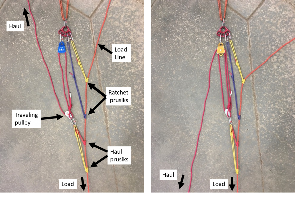
The operation of the piggyback uphaul is similar to the inline uphaul. The primary difference is that in addition to minding the ratchet prusiks, slack must be kept out of the load line. Two people are necessary to mind the ratchet prusiks: one keeps the prusiks extended as far as possible down the rope; the second pulls tension in the load line to keep slack out of the rope.
The piggyback uphaul system has some distinct advantages:
- If more than one rope length is required, passing knots through the system is relatively easy. The prusiks attaching the haul system to the load line can simply be taken off and retied below the knot joining the load lines. When the knot approaches the ratchet prusiks, the uphaul team maintains the belay while ratchet prusiks are installed below the knot. This may be a second set of ratchet prusiks or the original set may be detached and reinstalled below the knot. In either case, the uphaul team is the belay until the ratchet prusiks are fully installed below the knot.
- Transition between a lowering system and an uphaul system is simply a matter of attaching/detaching the piggyback uphaul system, exchanging the brake tube and the ratchet prusiks, and transitioning the load between systems.
The disadvantages of the piggyback uphaul system are that it requires a second rope and a second person to manage the ratchet prusiks. The inline system keeps the slack out of the load line during operation so a single person can tend the ratchet prusiks, but introduces the risk that the ratchet prusiks can be drawn into the pulley.
Alternative Change of Direction for Uphaul Systems
A double pulley is usually used for a 3 to 1 uphaul with a change of direction, but sometimes another configuration works better. The illustration below is shown with a piggyback uphaul system, but the same issues apply to an inline uphaul system.
3 to 1 with change of direction – haul team pulling downhill roughly parallel to load line 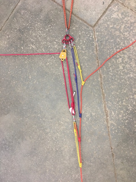
3 to 1 with change of direction – haul team pulling perpendicular to load line 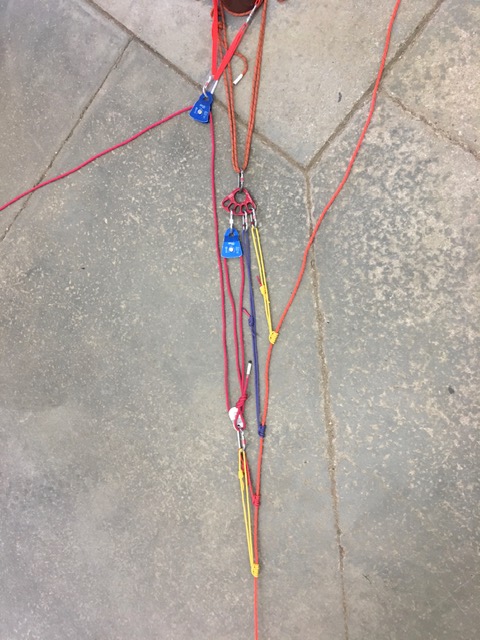
3 to 1 with change of direction – haul team pulling to the side with separate change of direction
- The left picture shows a 3 to 1 uphaul system with change of direction so the haul team can pull downhill roughly parallel to the load line. In this case, all of the ropes are in generally the same line.
- The center picture shows the same system, but the haul team is pulling to the side. This is undesirable because the force from the haul team tends to pull the anchor to the side. This makes it more difficult to tend the ratchet prusiks and generates effective slack due to the angle created in the load line and anchor. If the haul team relaxes and the load transfers to the ratchet prusiks (during a reset, for example), the load (litter) will move back downhill. This is especially pronounced if the anchor is relatively long.
- The right picture shows a 3 to 1 uphaul system with a separate change of direction attached to a separate anchor. The separate anchor can be attached to the same object (tree or rock) or a separate object. This allows the haul team to pull to the side while the main anchor, uphaul system and load line remain roughly in the same line. When the load is transferred to the ratchet prusiks, the downhill travel of the litter is reduced relative to the system in the center picture.
Uphaul Systems with Two Ropes
If two load lines are used in an uphaul system, a single piggyback uphaul system is attached to the two ropes. One ratchet prusik is attached to each rope. Similarly, one haul prusik is attached to each rope.
It is sometimes necessary to raise one rope at a time. This usually happens during a high angle rescue, but it could happen during a low angle rescue if slack develops in one line. This is accomplished by making sure the ratchet prusiks are locked, and loosening the haul prusik on the line that should NOT move and leaving the prusik locked on the line that SHOULD move. When the haul team pulls, only the rope with the locked haul prusik will move. When both ropes should move, simply lock both prusiks. Tending the ratchet prusiks is identical – both prusiks should be kept extended as far as possible from the brake.
Haul Team
The haul team generally ties into the haul line with prusiks or butterflies, although, if beneficial, the haul team may haul the litter up in a hand-over-hand method. This is generally useful if there is a small area for the haul team to work. However, if the haul team is to serve as the belay (independent of the ratchet prusiks), they must be tied into the haul line.
Especially if the haul team is tied in to the haul rope, the rule of 12 should be followed: the number of haulers multiplied by the mechanical advantage should be no more than 12. For a 3 to 1 uphaul system (mechanical advantage of 3), no more than four haulers should be used (3×4 = 12). This assumes good footing for the haul team – if the circumstances are such that the haul team cannot pull as hard (e.g., icy or otherwise slippery conditions) more haulers could be appropriate but it should be a considered decision.
Uphaul on a Bag
An uphaul system can be constructed separately from the load lines so it is ready when/if an uphaul is necessary. The 3-to-1 is constructed and attached to the rope bag, with only several feet of rope pulled out. This method can be faster than setting up an uphaul system by laboriously pulling all the rope out to its length. When the system is deployed, a member holds the rope bag and uphill pulley while another member pulls the traveling pulley/knot/prusiks to the point of attachment on the load line. The uphill pulley is attached to the anchor and the uphaul is complete.
Transition between Lowering and Uphaul
Sometimes a rescue starts with a lowering system and then an uphaul is required. For example, a vehicle has gone off a road with a steep embankment. A litter team is lowered to the subject, the subject is packaged and the litter must be uphauled back to the road. The piggyback system makes this transition simple even when the belay must be maintained at all times.
The first step is to install ratchet prusiks around the brake tube and remove the brake tube once the prusiks are set.
To transition from uphaul to lowering, reinstall the brake tube above the set ratchet prusiks – do not remove the uphaul system yet. Once the brakeman is ready to accept the belay, use the uphaul system to raise the load just enough to allow the release of the ratchet prusiks. While minding the ratchet prusiks so they do not lock, the haul team lowers the load until it transfers to the brake; the brakeman should HOLD the load, not continue lowering the load. Once the load is fully transitioned to the brake and the brakeman has the belay, the uphaul system (including ratchet prusiks) can be removed. The transition from uphaul to lowering is complete.

