
There are many forces in a rescue system. It is important for you to know these forces and the working loads. It is important to know that knots are weak points and account for that weakness. We design our systems stronger than they need to be by using a “Factor of Safety”.
Forces
In America, we’re used to measuring forces in pounds. When you step on a scale, earth’s gravity pulls on the mass of your body and we measure it in pounds. The metric system measures force in Newtons (N) or in thousands of Newtons (kN).
1 Newton(N) = 0.225 pounds
1 kiloNewton (kN) = 225 pounds
Since most of the world uses the metric system, the capacity of mountaineering and climbing gear is often given in kN.
Strength of equipment
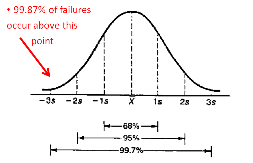
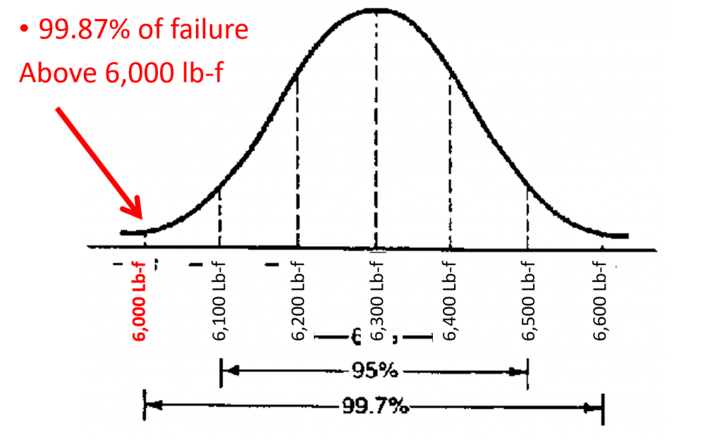
When ropes, carabiners and other kinds of gear are manufactured, not every similar piece will break at the same load. Many similar pieces are tested to failure, and the number of pieces that break at each load are graphed as shown in the illustration below. Presumably, the most failures will occur at the average load (the high point on the curve), and the number that break at a given load will decrease as you move away from the average. 99.7% of all breaks will occur 3 “standard deviations” on either side of the average. The Minimum Breaking Strength (MBS) is defined as the average breaking strength less 3 standard deviations, which gives 99.87% confidence that the breaking strength is greater than the reported MBS.
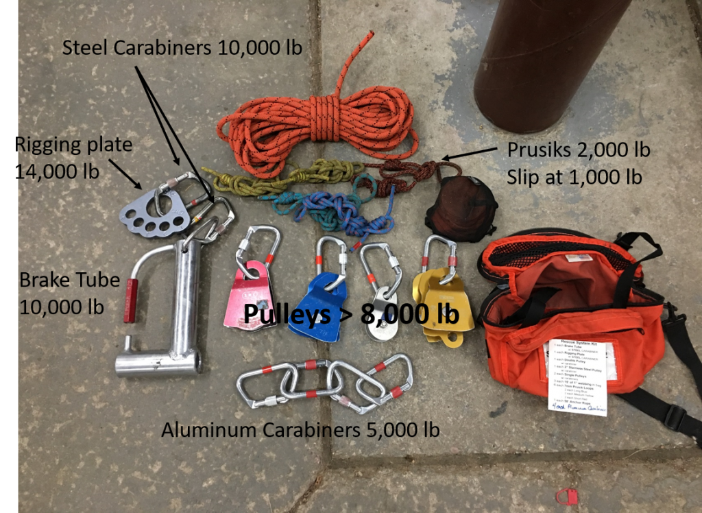
The gear used by EPCSAR has the following minimum breaking strength:
- 11mm Static Rope = 6,000 Lb-f
- 1” tubular webbing = 4,000 Lb-f
- 7mm Prusik cord = 2,000 Lb-f
- Aluminum carabiner > 22kN = about 5,000 Lb-f
- Steel carabiner = 10,000 Lb-f
- Other system components > 8,000 Lb-f
When purchasing gear, look for gear that meets these minimum values. This ensures that if you use a piece of your personal gear in a rescue system, it is at least as strong as the team gear. The picture below shows the strength of each piece of gear in a rescue pack.
Of course, the MBS applies to new gear in good condition. A piece of gear that is worn or damaged will almost certainly have a lower MBS. For this reason, systems are designed with a Factor of Safety as discussed shortly.
Carabiner strength
The strength of a carabiner depends upon how it is loaded. The image below shows the marking on a sample carabiner:
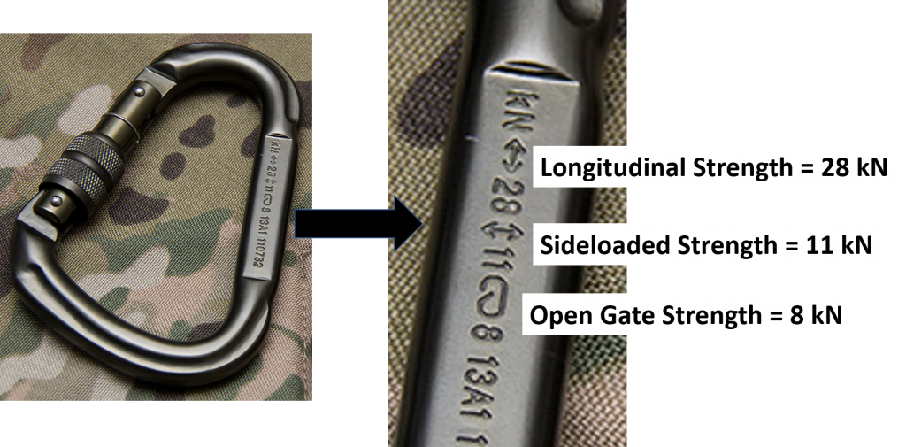
Always load a carabiner in the longitudinal direction and ensure the gate is closed.
Knots
Knots are used in every system and weaken the breaking strength of our ropes. Some knots weaken ropes less than others. Conservatively, and to simplify the math, we assume that a knot weakens a rope 50%. If an 11mm static rope has a mean breaking strength of 6,000 pounds, adding a knot reduces the strength to 3,000 pounds.
6,000 pounds X 50% for the knot = 3,000 pounds
Similarly, a rope is weakened when it is bent around an object. The sharper the bend, the more the rope is weakened. When a rope is bent around an object approximately the diameter of the rope, the reduction in strength is approximately 50%. Therefore, when a rope passes over a carabiner, the strength is reduced by about 50%. Larger diameter bends do not affect the rope strength as much, so pulleys are usually not considered to significantly weaken the rope. Sharper bends weaken the rope more, so any sharp edge will weaken the rope dramatically.
Since a rope will either pass over a carabiner or have a knot in it to be of any use, assume ropes are always weakened by 50%. If a rope or piece of webbing has a knot and passes over a carabiner, the strength reduction is not additive. Consider the piece of material as a chain with a weakest link. The presence of multiple weak links does not affect the overall strength – it will fail at its weakest link.
Factor of Safety (FoS)
Systems are purposefully built stronger than needed for normal usage to allow for emergency situations, unexpected loads, misuse, or degradation. How much stronger is known as the “Factor of Safety”. In EPCSAR, we use a factor of safety of four (4). We design the systems to handle four times the loads that we expect. Another way of looking at it, is to say that we expect the gear to only hold one fourth of what it is rated to hold. If an 11mm static rope has a mean breaking strength of 6,000 pounds, adding a knot reduces the strength to 3,000 pounds. If we design our system to only put one fourth of that load on the rope, the safe working load for that single rope is 750 pounds.
6,000 pounds X 50% for the knot = 3,000 pounds
3,000 pounds ÷ factor of safety of four = 750 pounds
If we use a component rated for 22kN, we design our system to only put one fourth of that load on that component;
22 kN = 4,950 pounds
4,950 pounds ÷ 4 FoS = 1237 pounds
If we assume that a conservative estimate for the average EPCSAR rescuer is 225 pounds with personal gear and pack, the maximum force that rescuer puts on a system is 1 kiloNewton. If our Factor of Safety is 4, we’d need 4 kN to support that one rescuer alone. If you divide a load rating of a specific piece of gear by 4 kiloNewtons, you can get an idea of how many rescuers it will safely support;
22kN ÷ 4 FoS = 5.5 kN
If 1 kN = 225 pounds = 1 rescuer ∴
One 22 kN piece will support 5+ rescuers safely.
Tension in rope
Forces in rescue systems are determined by the tension in the ropes. As discussed in the previous section, the tension in an 11mm static rope should never exceed 750 lb. But depending upon the system geometry, the forces exerted on an anchor or litter may be much larger or smaller than the tension in the rope.
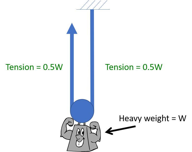
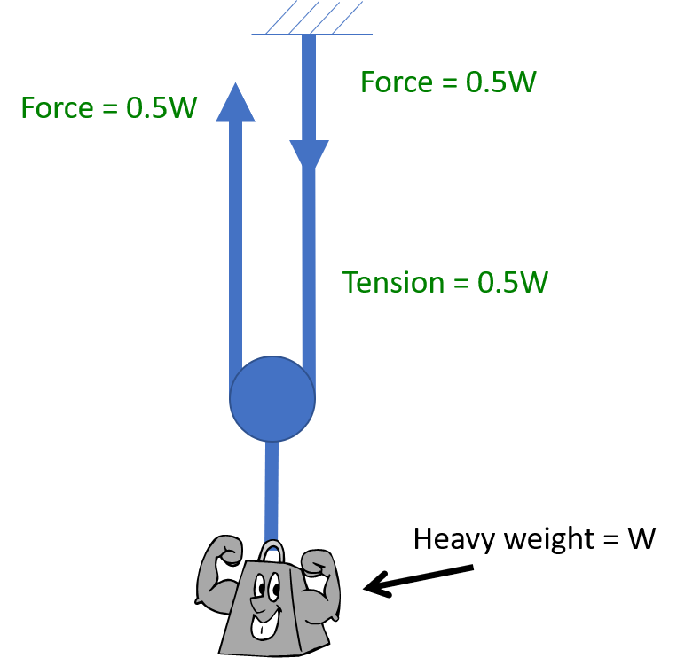
Consider the arrangement below. A rope is fixed at an anchor and supports a weight suspended by a pulley. A haul team is exerting force upward to keep the weight from falling. Each “leg” of the rope supports half the weight, so the tension in the rope is 0.5W. The force on the anchor is 0.5W, as is the force exerted by the haul team.
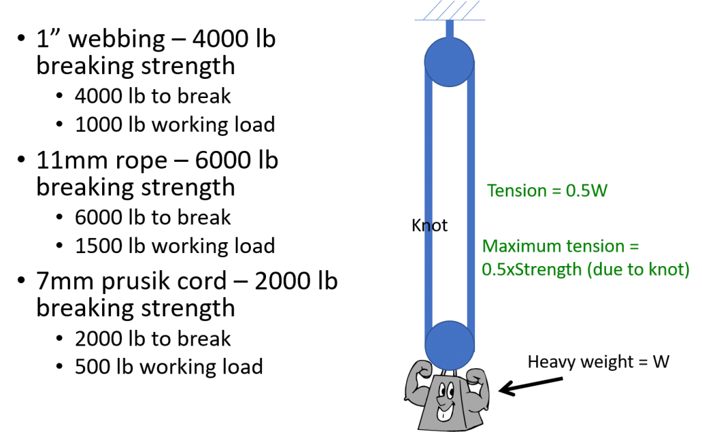
Now consider the strength of a sling made of various materials supporting a weight as illustrated below. There is a knot in the sling, so the maximum tension is reduced by 50%. How much weight can be applied before the maximum tension in the material is reached? There are two “legs” of material supporting the weight, so the tension in the material is half the weight. Since the maximum tension is half the minimum breaking strength, the sling can support a weight equal to the minimum breaking strength of the material. The “working load” is defined as the strength of the sling divided by the factor of safety.
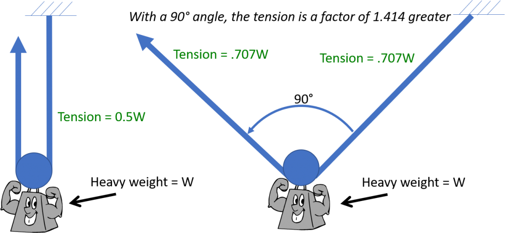
In the previous illustration, the angle between the ropes is zero. What happens if the angle between the ropes increases? In the illustration below, the angle between the legs in the right illustration is 90 degrees. The tension in the rope is 1.414 times that of the tension if the angle is zero.
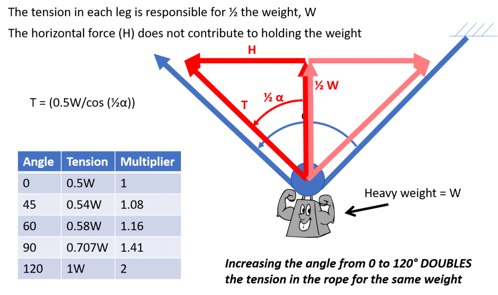
Why does this happen? In the next illustration, the tension in the rope is broken into its force components. The vertical component is supporting the weight, and the horizontal component is simply “balancing” the horizontal component of the opposite rope. The vertical component of the tension in each rope must be half the weight. As the angle increases, more tension is required to support the weight. The table summarizes the tension in the rope for various angles. At 120 degrees, the tension in the rope is equal to the weight supported. The tension increases quickly as the angle exceeds 120 degrees.
Forces in Systems – Lowering
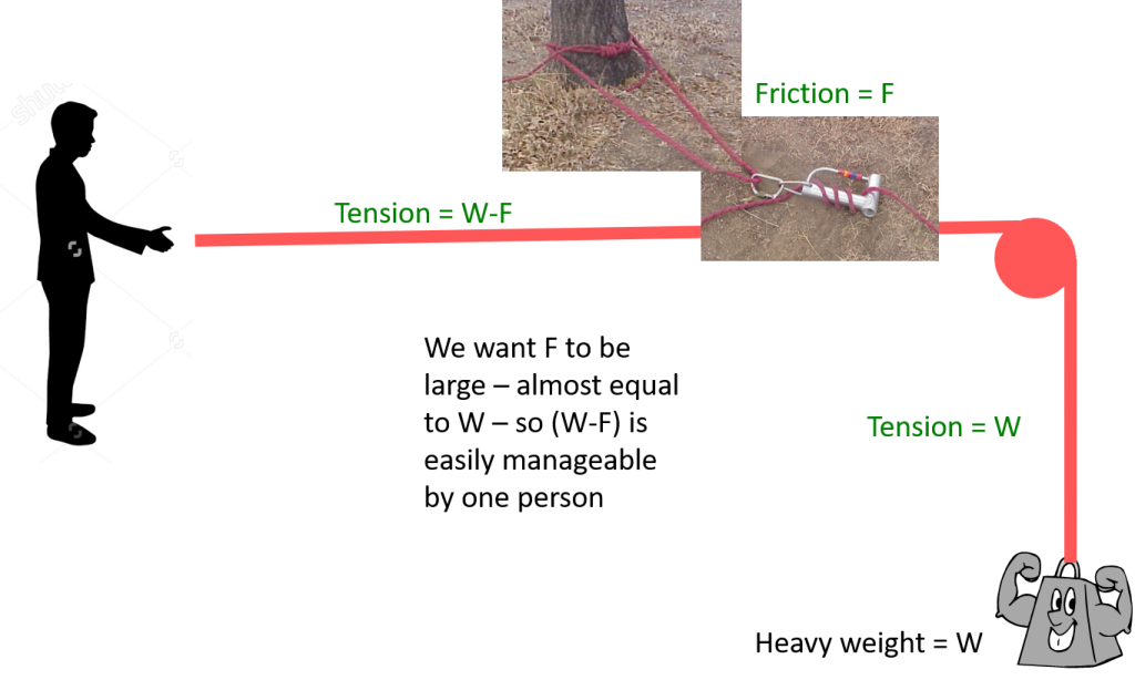
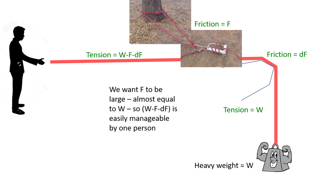
Looking at a lowering system, the forces in the system are the weight of the load (litter and people) and the friction of the brake device. In this case, the friction “F” reduces the tension in the rope. F should be nearly as much as W so that the tension at the brakeman is small – manageable by one person. As shown in the right image, any edge friction helps reduce the load on the brakeman (and the anchor) but edge friction usually comes with a risk of rope damage so it should be avoided. The maximum force on the anchor in a lowering system is generally the weight of the load. A shock load can increase this dramatically, so slack should be kept out of the system unless the litter team asks for slack.
Forces in Systems – Uphaul
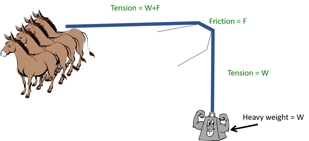
A simple uphaul is illustrated below. Unlike a lowering system, any edge friction INCREASES the tension in the rope at the haul team, thereby increasing the effort required by the haul team to raise the load. The friction can be quite large, so devices like edge rollers are used to reduce the friction. In some cases, without edge rollers, the friction will cause the tension in the rope to exceed the maximum allowable. Generally the tension in the rope at the load will be equal to the load.

Mechanical advantage is used to decrease the load required for a haul team to raise a load. Mechanical advantage and uphaul systems are discussed earlier in this chapter. Here, we will look at the forces on the anchor for various mechanical advantage.
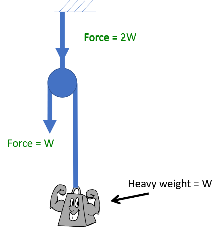
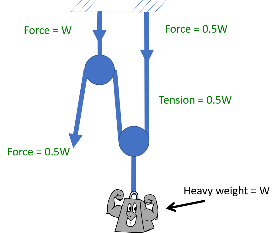
In the previous illustration, there is no mechanical advantage and the haul team essentially provides the uphaul force AND the belay. Usually a 1 to 1 uphaul uses a change of direction pulley at an anchor so that ratchet prusiks can be added. 1 to 1 and 2 to 1 mechanical advantage systems are illustrated below. A 1 to 1 uphaul with a 180 degree change of direction produces a force on the anchor equal to twice the weight. Turn this around and create a 2 to 1 mechanical advantage uphaul and the load on the anchor is HALF the weight. The haul team carries the other half. Add a change of direction to the 2 to 1 mechanical advantage, and the load on the change of direction is equal to the weight – 2 times the tension in the rope (0.5W). If the change of direction is on the same anchor, the net force on the anchor is 1.5 times the weight. In each of these cases, if the load is resting solely on ratchet prusiks attached to the anchor, the load on the anchor is equal to the weight.
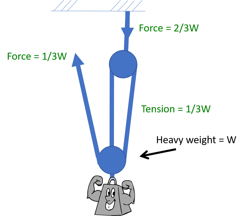
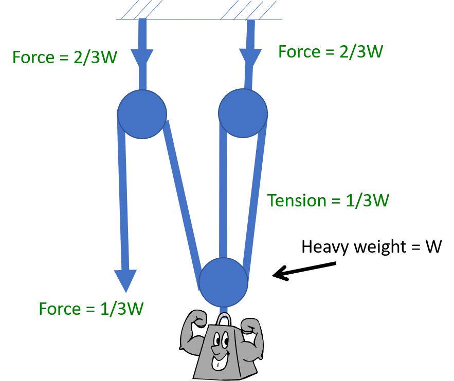
A 3 to 1 mechanical advantage with and without change of direction is illustrated below. Without a change of direction, the force on the anchor is 2/3 of the weight. Recognize that if the system is resting on a ratchet prusik, the load on the anchor will be equal to the weight. Adding a change of direction creates an additional anchor force of 2/3W. If this is located on the same anchor, the net load on the anchor is 4/3W. Again, if the system is resting on a ratchet prusik, the load on the anchor is equal to the weight.
In general, adding a change of direction to the same anchor will greatly increase the load on that anchor. If the change of direction can be placed on a separate anchor (impossible with the 1 to 1), this reduces the load on the primary anchor.
The primary anchor must always be capable of supporting the full weight of the load as the ratchet prusiks will need to be placed on the primary anchor (except in the case of the 2 to 1). Realize, too, that the force exerted during the uphaul will include any edge friction (almost never zero) so the anchor must be capable of sustaining that load. Once the system is resting on ratchet prusiks, the edge friction no longer acts to increase the tension.
Strength of EPCSAR Systems – Anchors
The main anchors used in EPCSAR systems are shown below. All have four legs supporting the load. Assuming the angle is small between the outer legs of the anchor, the strength of the anchor is 4 times the strength of the material, but the strength is decreased by 50% because of the presence of knots and carabiners. Therefore, the strength of the anchor is 2 times the minimum breaking strength of the material itself. Taking into account a factor of safety of 4, the working load on the anchor is half the minimum breaking strength of the material. If aluminum carabiners are used in a basket anchor, the strength of the carabiners will be about 5000 lb. The carabiner joining the two ends of the webbing sling is stronger than the webbing sling, so it will not be the weak link. However, the carabiner at the load point carries all the load, so the working load of a basket anchor with aluminum carabiners is 1250 lb.
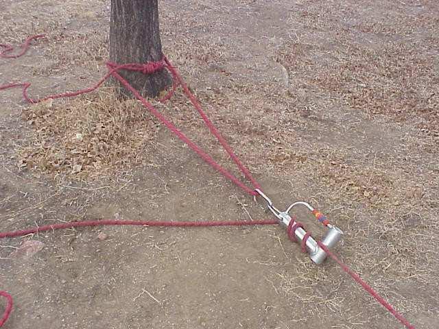
Wrap 3 pull 2 strength 12000 lb,
working load 3000 lb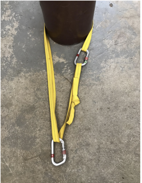
Basket anchor strength 8000 lb,
working load 2000 lb, or 5000/1250 lb with aluminum carabiner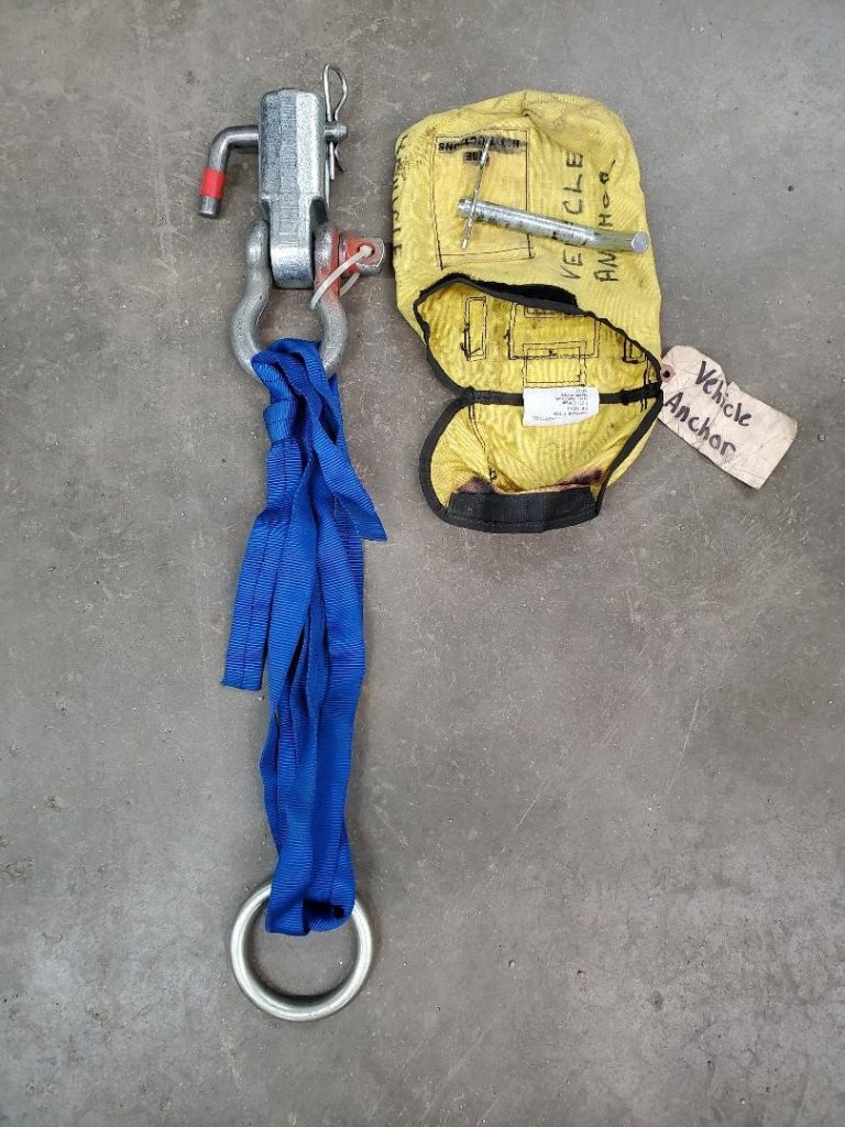
Vehicle anchor strength 8000 lb,
working load 2000 lb
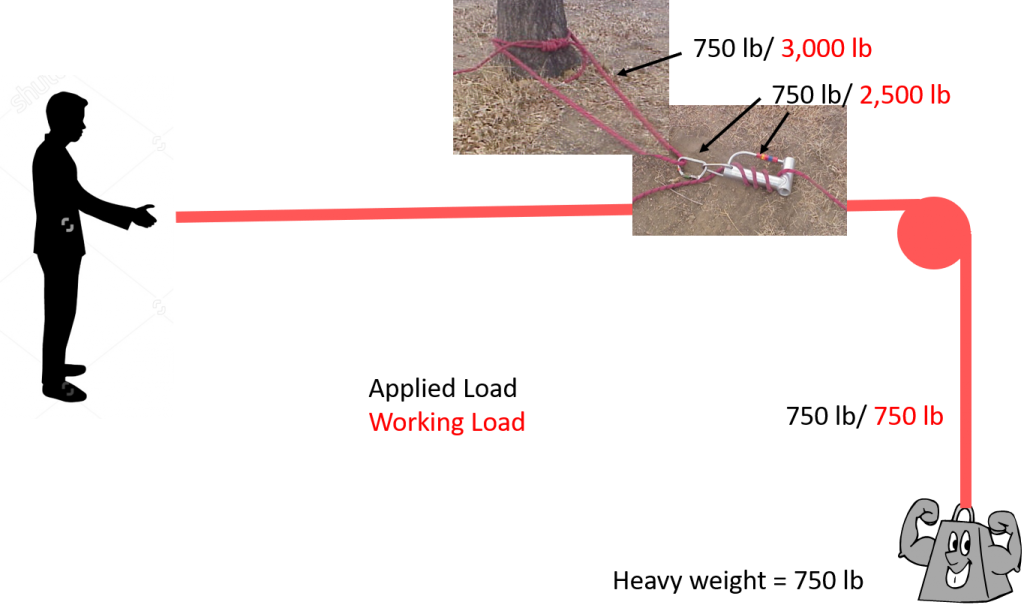
Strength of EPCSAR Systems – Lowering System
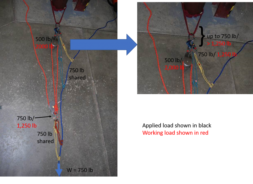
The forces in a lowering system are fairly simple and are illustrated below. The applied load is shown in black and the working load is shown in red. Notice that as long as the load does not exceed 750 lb, the forces in the system remain below the working load of the components. If a basket anchor is used in place of the wrap 3 pull 2 as shown, the working load may be 1250 lb (if aluminum carabiners are used), but this is still above the applied load.
Strength of EPCSAR Systems – Piggyback Uphaul System
The piggyback uphaul system is illustrated below. The forces in the system are more complicated than for a lowering system. As before, the applied load is shown in black and the working load is shown in red. A load of 750 lb is assumed. The applied load at each point is less than the working load. If a change of direction is included in the haul system, the applied load at the fixed pulley and the anchor increases to 1000 lb which is still less than the working load of at least 1250 lb. Of course, this assumes that the object used as an anchor can withstand at least as much force as the components.
No working load is assigned to the prusiks in the illustration. Each set of prusiks (ratchet and haul) could share as much as 750 lb, and each have a working load of 500 lb. Additionally, the prusiks should slip at approximately 1000 lb.
Considering the haul prusiks, they share 750 lb of load. Together they have a working load of 1000 lb, and if one were to begin to slip it will transfer load to the other. It is impossible to predict how much each prusik will carry in a given situation as they probably won’t have equal load, but they will share the load. The double prusiks also provide redundancy.
Considering the ratchet prusiks, they also could theoretically share 750 lb, but probably less. There will almost certainly be friction in any practical uphaul system. Therefore, the haul prusiks will carry more load than the ratchet prusiks. If the haul prusiks begin to slip, the ratchet prusiks should hold. Each pair of prusiks is by itself redundant. So for a system failure, all four prusiks would have to fail.

